Posts

Showing posts from September, 2023

FILE TRANSFER PROTCOL

Image
  File Transfer Protocol(FTP) is an application layer protocol that moves files between local and remote file systems. It runs on top of TCP, like HTTP. To transfer a file, 2 TCP connections are used by FTP in parallel: control connection and data connection. Why FTP? FTP  is a standard communication protocol. There are various other protocols like HTTP which are used to transfer files between computers, but they lack clarity and focus as compared to FTP. Moreover, the systems involved in connection are heterogeneous systems, i.e. they differ in operating systems, directories, structures, character sets, etc the FTP shields the user from these differences and transfers data efficiently and reliably. FTP can transfer ASCII, EBCDIC, or image files. The ASCII is the default file share format, in this, each character is encoded by NVT ASCII. In ASCII or EBCDIC the destination must be ready to accept files in this mode. The image file format is the default format for transforming binary fil

Reflex Sensor and it's Applications

Image
  Reflex Sensor A simple reflex sensor has transmitter and receiver sections. The transmitter sensor emits a light beam and when an object is detected the receiver captures and process this as changeover signal. Applications : Monitors flow of material process Level measurement Print and Color detection Inspection of Assembly Sealing cap monitoring Recording level of liquid quantities

TA 2003 FM Radio Receiver

Image
  big! Here is a simple FM Radio Receiver Using single chip TA 2003. This IC have inbuilt RF Amplifier, local oscillator, a mixer, FM detector and AF preamplifier. Only few passive components like ceramic capacitors, X1, X2 both are 10.7MHz 3-pin, 2-pin, homemade inductors like L1, L2 and L3,an electrolytic capacitor 2.2uF/25V are used in this circuit. 10.7 MHz IFT coil is not used here so there is no need to tune of coils. Parts List Semiconductors IC1: TA 2003 Ceramic capacitors C1: 47pF C2: 103 C5: 0.01uF VC1a, b: 20-30 pF FM gang capacitor Electrolytic Capacitor C3:10uF/25V C4(220uF/25V) Ceramic Filter 2-pin and 3pin 10.7 MHz ceramic filters Miscellaneous 2-pin connectors, 2*1.5 volts battery case a battery, 75cm long wire, 22 SWG copper wire, 16pin IC socket and vero board 5cm* 7cm e.t.c. Circuit Description Pin 1 of IC1 TA 2003 is connected to antenna (75cm long wire) through C1. A capacitor C3 is c. Pin 2, pin 9 are grounded. A crystal 10.7 MHz 3-pin is connected to pin 3 and 8

Why Do Circuit Breakers Trip?

Image
HOME ABOUT US SERVICES SPECIALS REVIEWS SCHEDULE SERVICE Why Do Circuit Breakers Trip? Circuit breakers are a protective measure against damage to a circuit in the event of an electrical current overload. In other words, it makes sure that nothing breaks if you have too many appliances on at the same time and cause a short circuit. The circuit breaker is an electrical switch that connects to your homes circuit board and interrupts the flow of electrical current if it detects a fault. In the event of a fault, the breaker switch will automatically stop the electricity from flowing through the circuit. Circuit breakers are designed to ensure that a short circuit does not cause damage to the home or building. Before circuit breakers, in the event of a power surge, you had to replace a blown fuse. Fuses also protected against electrical fires but only once and then you had to replace the blown fuse. With a circuit breaker once you correct the issue that caused the power surge or fault yo ca

Linear Induction Motor

Image
   Linear Induction Motor: The  induction motor  is used to convert the  electrical energy  into rotation energy. Another form of induction motor is a linear induction motor. It is used to convert electrical energy into linear motion. The linear induction motor is known as LIM.  It operates on the principle of electromagnetic induction.  This type of motor is most popular in traction applications.  Similar to the regular induction motor, the linear induction motor also has two windings; primary winding and secondary winding.  In most cases, the primary winding is made up of copper and the secondary winding is made up of aluminum. The  three-phase induction motor  produces linear progressive motion and the single-phase induction motor produces oscillatory motion.

Weighing Sensors

 Load cell (weighing sensors) Weighing Sensor Load cells measures and process the weight. There are different types of load cell sensors based on usage of the application. Some of them are: Beam Load cells (Bending Load cell) These are suited for normal weight measurement applications and industrial-weight measurement. Applications of beam load cell are To fill the machinery Tank weighing Vehicle Onboard weight Medical equipment Bed weighing To package machinery Single point Load cell Single point load cells are used for low weight systems. Applications: Bench and retail scaling Waste collection Package and filling machinery Compression Load cell These are suitable for high weight scaling systems. Applications: Medical devices Measuring equipment Pump controlling devices Railway weight checkers

REMOTE TERMINAL UNIT

Image
  A remote terminal unit  ( RTU ) is a  microprocessor -controlled electronic device that interfaces objects in the physical world to a  distributed control system  or  SCADA  (supervisory control and data acquisition) system by transmitting  telemetry  data to a master system, and by using messages from the master supervisory system to control connected objects.  Other terms that may be used for RTU are  remote telemetry unit  and  remote control unit . Applications of RTU Remote monitoring of functions and instrumentation for: Oil and gas (offshore platforms, onshore oil wells, pump stations on pipelines) Networks of pump stations (wastewater collection, or for water supply) Environmental monitoring  systems (pollution, air quality, emissions monitoring) Mine sites Air traffic equipment such as navigation aids Hydro-graphic (water supply, reservoirs, sewage systems) Electrical power transmission networks and associated equipment Natural gas networks and associated equipment Outdoor w

Clipper Circuit

Image
Clipper Circuit A clipper circuit clips off or removes a portion from an AC signal without distorting or changing the remaining part of the waveform. It limits the voltage from rising above or below a certain point. Therefore, it is also used for protection against overvoltage. The clipper circuit can be also known as a clipper, clipping circuit, voltage limiter or slicer, etc. A clipper circuit is made of a diode, resistor. The diode is used for chopping or clipping a portion of the signal’s waveform. A clipper circuit can be either series clipper or shunt clipper where both types can be used to clip either half of a waveform or clip a portion from the waveform. The change in the shape of the waveform depends on the type of the clipper circuit. A clipper circuit does not change the amplitude of the waveform. It only blocks the amplitude from rising above a certain limit which is why it is also known as a voltage limiter. A clipper can be either positive or negative. A positive clipper

Limit Switch

Image
  What is Limit Switch? Limit switch definition is an electromechanical switch that operates by any physical force or the movement of a machine.  These switches are very helpful in detecting the absence or presence of an object, counting, detecting speed, detecting movement range, travel limit, positioning, etc.  These switches include three terminals NO (Normally Open), NC (Normally Open) & Common. Limit Switch The controlling of this switch can be done by different factors like temperature, position, and pressure. This switch is mainly designed to operate only once a fixed limit is achieved, and it is generally activated through contact by using an object like a  cam.

OLTC diagnosis

  OLTC diagnosis Electrical field tests: Exciting current ;   exciting current tests have the ability to detect a myriad of transformer tap changer problems (DETC and OLTC), including: misalignment, coking and wear of contacts, loose moveable contacts, improper wiring from the tap winding to the OLTC, reversed connections to the preventative autotransformer (PA) of an OLTC, open- or short-circuited turns or high resistance connections in the OLTC PA, series autotransformer or series transformer, and more. DC winding resistance ; a DC winding resistance test is used to detect any problem which impacts the integrity of the current carrying path between terminals of a winding, including the tap changer.  It is particularly adept in identifying partial open-circuited conditions. Dynamic winding resistance ; a dynamic winding resistance test is the measure of the DC current and resistance (as a function of time) as the OLTC changes tap position.  It is particularly effective at identifying

Analog Hall effect/Magnetic Sensor (Position Sensor)

Image
 Analog Hall effect/Magnetic Sensor (Position Sensor) Hall Effect Sensor The Hall Effect sensor works on the magnetic field. It senses the magnetic field and gives the output voltage. When the magnetic field is positive output voltage increases above the null voltage (no magnetic field and zero current). Applications of Hall sensor are: GPS positioning Current sensing Speed movement detection Magnetic code decoder Metal detector Controlling motors

Digital Storage Oscilloscope

Image
  What is Digital Storage Oscilloscope? Digital storage oscilloscope definition is an electronic device that stores and analyses the signal in the digital format is known as Digital Storage Oscilloscope (DSO). When the input signal is given to the DSO, then it is processed, stored in the memory, and displayed on the screen. It stores the signal in the form of digital data as either 1 Or 0. Block Diagram The  block diagram of the Digital Storage Oscilloscope  is shown below. Digital Oscilloscope Block Diagram

Engineer’s Day

Image
In India, we celebrate Engineer’s Day on September 15, as a tribute to the greatest Indian Engineer Bharat Ratna Mokshagundam Visvesvaraya. Here are the 5 facts you should know about Mokshagundam Visvesvaraya . * From 1912 to 1918, M. Visvesvaraya was appointed as the Diwan of Mysore. He was the chief engineer responsible for the construction of the Krishna Raja Sagara Dam in Mysore. Under his Dewanship, Mysore had undergone a major transformation in the realms of agriculture, irrigation, industrialization, education, banking and commerce. * He completed his graduation in Bachelor of Arts (BA) from the University of Madras, done civil engineering from College of Science in Pune. * He designed and patented automatic water floodgates in 1903, which were first installed at the Khadakwasla reservoir, in Pune. * He was a renowned precursor of economic planning in India. * In 1917, Visvesvaraya established Government Engineering College in Bengaluru which was later named University Visvesvar

PLC MANUFACTURES

Image
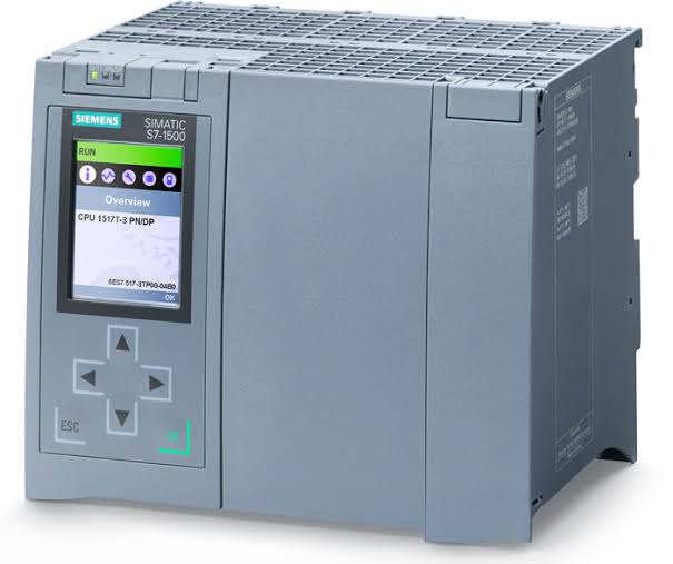
The brand of  Siemens PLC   is at the topmost position. And  Allen Bradley (AB) PLC  is at the second position in Automation. Allen Bradley PLC is popularly known as  Rockwell PLC . 01  AB PLC United State RS Logix (RS Logix 5, RS Logix 500 and RS Logix 5000) 02 Siemens PLC Germany Step 5- Micro wins Step 7- Simatic Manager 03 ABB PLC Switzerland Automation Builder AC010 AC500 04 Delta PLC Taiwan WPL Soft ISP Soft 05 Schneider PLC Europe PL7 TwidoSuite ProWORX 32 06 Mitsubishi PLC Japan Gx Developer Gx Works 2 MELSOFT series 07 Omron PLC Japan CX-One CX programmer 08 Hitachi PLC Japan EH-150 09 General Electric PLC United State Durus 10 Honeywell PLC United State HRA 11 FATEK PLC Taiwan WinProladder 12 Bosch Germany Bosch Rexroth