Clipper Circuit
Clipper Circuit
A clipper circuit clips off or removes a portion from an AC signal without distorting or changing the remaining part of the waveform. It limits the voltage from rising above or below a certain point. Therefore, it is also used for protection against overvoltage. The clipper circuit can be also known as a clipper, clipping circuit, voltage limiter or slicer, etc.
A clipper circuit is made of a diode, resistor. The diode is used for chopping or clipping a portion of the signal’s waveform.
A clipper circuit can be either series clipper or shunt clipper where both types can be used to clip either half of a waveform or clip a portion from the waveform. The change in the shape of the waveform depends on the type of the clipper circuit.
A clipper circuit does not change the amplitude of the waveform. It only blocks the amplitude from rising above a certain limit which is why it is also known as a voltage limiter.
A clipper can be either positive or negative. A positive clipper clips the positive half of the AC waveform & the negative clipper clips the negative half. The circuit can be modified with another voltage biasing to further modify the signal’s waveform.
Here is a positive series clipper circuit.
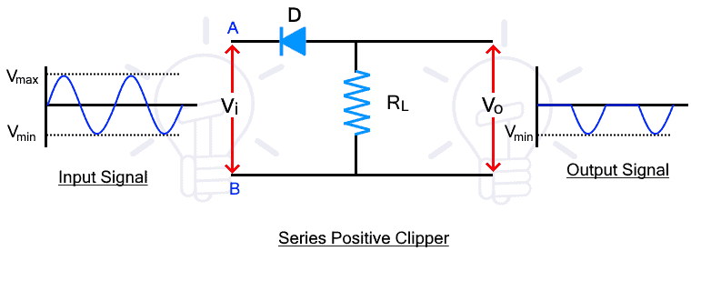
During the positive half, the diode is reverse biased & it does not conduct the signal to the load resistor. But during the negative half, the diode becomes reverse bias for the input signal & it conducts. Therefore, the positive half does not appear at the output while the negative half does. In other words, the positive half has been clipped from the input signal.


Comments
Post a Comment