TA 2003 FM Radio Receiver
big!
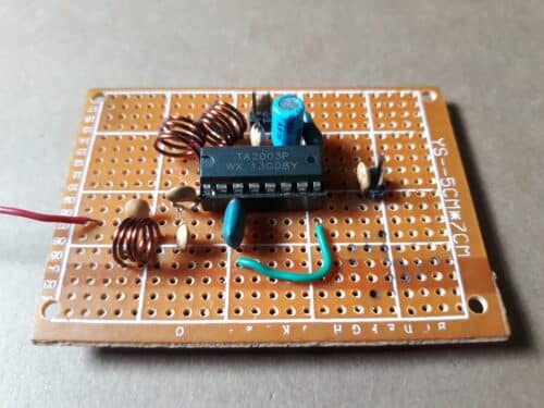
Here is a simple FM Radio Receiver Using single chip TA 2003. This IC have inbuilt RF Amplifier, local oscillator, a mixer, FM detector and AF preamplifier. Only few passive components like ceramic capacitors, X1, X2 both are 10.7MHz 3-pin, 2-pin, homemade inductors like L1, L2 and L3,an electrolytic capacitor 2.2uF/25V are used in this circuit. 10.7 MHz IFT coil is not used here so there is no need to tune of coils.
Parts List
| Semiconductors IC1: TA 2003 Ceramic capacitors C1: 47pF C2: 103 C5: 0.01uF VC1a, b: 20-30 pF FM gang capacitor Electrolytic Capacitor C3:10uF/25V C4(220uF/25V) Ceramic Filter 2-pin and 3pin 10.7 MHz ceramic filters Miscellaneous 2-pin connectors, 2*1.5 volts battery case a battery, 75cm long wire, 22 SWG copper wire, 16pin IC socket and vero board 5cm* 7cm e.t.c. |
Circuit Description
Pin 1 of IC1 TA 2003 is connected to antenna (75cm long wire) through C1. A capacitor C3 is c. Pin 2, pin 9 are grounded.
A crystal 10.7 MHz 3-pin is connected to pin 3 and 8 (colour tag is faced towards pin 3) and middle pin is connected to+3 Vcc.
Pin 13 is connected to coil L2 and VC1b in parallel to each other . Other one end is connected to +3 Vcc. Pin 6 and pin 14 are connected to +3Volts. A coil L1 and VC1b are connected to each other in parallel. One end of L1 and VC1a is connected to pin 15 and others end is connected to +3Vcc. Pin2, 9 are grounded.
Ceramic filter X2 (10.7 MHz 2-pin) is connected to +3 Vcc and pin 10. Pin 11 is an output pin and is connected to AF amplifier through an electrolytic capacitor 10uF/25V. A capacitor C4 is an electrolytic capacitor is of (220uF/25V) connected to negative terminal and +3Vcc which will filter a DC +3Vcc.voltage. And capacitor C2 will filters a noise represent at AF output. And an AF output is taken output from pin 11 of IC1 through an electrolytic capacitor C3 (10uF/25V).


Comments
Post a Comment